Volkswagen Touran Service Manual: Refrigerant Circuit, Tracing Leaks, with Leak Detection System -VAS6196- or
Leak Detection Kit -VAS6201A- or Succeeding Model
 Note
| This repair manual describes different methods for detecting
leaks in the refrigerant circuit. These methods have been tested
and result in success when used correctly. |
| If when searching for compressed air / Nitrogen or vacuum
leaks none are found, add a leak detection additive i.e UV leak
detection additive, to the electric leak detecting unit. |
| Minor leaks can be detected using an electronic leak
detector or UV leak detector lamp. |
| Many methods for detecting leaks in the refrigerant circuit
are offered in the open market. These methods do not always have
optimum results. If they are not used exactly according to
specifications, they can indicate refrigerant circuit components
have leaks even when they do not. Also, refrigerant circuit
components can be damaged by some methods. |
| Do not repair components with leaks. Replace them with new
original parts. |
| Do not charge a leaking refrigerant circuit with
refrigerant. Evacuate the circuit and check it for leaks before
charging. Refer to
→ Chapter "Refrigerant Circuit with A/C Service Station,
Draining". |

Caution
| If it is suspected that chemicals were added to the
refrigerant circuit to seal leaks, do not connect the
A/C service station and do not extract the refrigerant. |
| Chemicals that seal leaks in the coolant circuit
form deposits that affect the function of the A/C system
and lead to failure of the A/C system and the A/C
service station. |
| Inform that customer that there are substances in
the A/C system that are no approved by Volkswagen. This
A/C system cannot be drained or serviced in the
workshop. |
|
Note
| VW does not approve the use of chemicals to seal leaks in
the refrigerant circuit. |
| Chemicals used to seal leaks in the refrigerant circuit
often react with air and the moisture in it. They cause deposits
in the refrigerant circuit and the A/C service station and
malfunctions in valves and other components that they come in
contact with. These deposits cannot be removed completely from
the components, even by flushing. |
| Chemicals used to seal leaks in the refrigerant circuit
usually cannot be detected from outside. The label that should
be applied to identify it is often missing. Therefore be careful
when working with if you do not know its service history. |
| Accessories offer containers used to separate out these
chemicals (used to seal leaks in the refrigerant circuit).
Because VW does not approve the use of these chemicals, there is
no evidence of the effectiveness of these filters. |
Note
| Small leaks can be detected using a UV-leak detection
additive for example. |
| |
Discharge the refrigerant circuit with the A/C service
station. Refer to
→ Chapter "Refrigerant Circuit with A/C Service Station,
Draining". |
Note
| Be ready to evacuate a large leak should one be found. Refer
to
→ Chapter "Refrigerant Circuit with A/C Service Station,
Draining". |
| If no leak is found during evacuation or there is a leak
that is so small that the location cannot be found, proceed as
follows. Refer to
→ Chapter "Searching for Refrigerant Circuit Leaks with
Compressed Air or Nitrogen". |
| Currents of air quickly disperse refrigerant gas. Draughts
must therefore be avoided during leak detection. |
| If the refrigerant circuit is completely empty, fill with
refrigerant to approximately 10% of the fill capacity (R134a
label or vehicle-specific Repair Manual). |
|
|
|
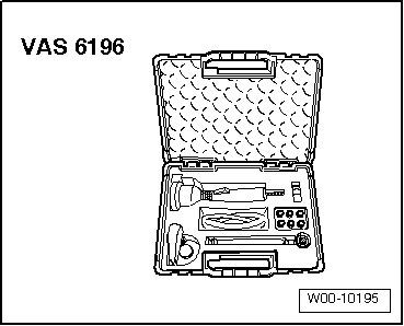
| Leak Detection System -VAS6196- |
|
|
|
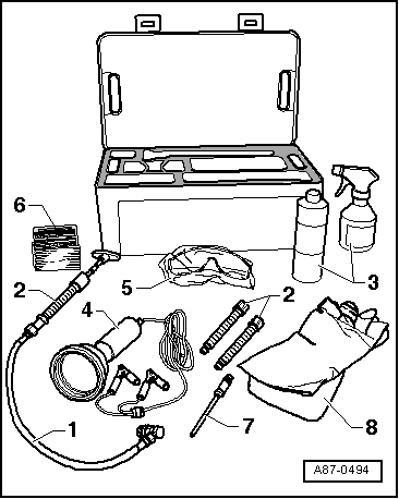
| Leak Detection System -VAS6201- or succeeding model |
| 1 - |
Leak Detection Kit - Hand Pump w/Cartridge -VAS6201/1- |
| 2 - |
Leak Detection Kit - Cartridge -VAS6201/2- |
| 3 - |
Leak Detection Kit - Cleaning Solution -VAS6201/3- |
| 4 - |
UV Leak Detection Lamp -VAS6201/4A- |
| 5 - |
Leak Detection Kit - Eye Protection -VAS6201/6- |
| 6 - |
Leak Detection Kit - Label -VAS6201/7- |
| 8 - |
Leak Detection Kit - Hand Protection -VAS6201/9- |
|
|
|
| Filling with leak detection additive when the refrigerant
circuit is empty |
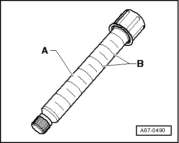
| The cartridge -A- contains 15.4
ml of leak detection additive (one unit
-B- corresponds to 2.5 ml). |
|
|
|
| |
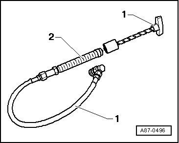
Assemble the Leak Detection Kit -VAS6201A--1-
with the cartridge -2-Leak
Detection Kit - Cartridge -VAS6201/2-. |
| |
Insert the Leak Detection Kit - Filler Tube -VAS6201/8- into
the hand pump. Refer to
→ Anchor-7- |
| |
Open the hand pump service valve. |
|
|
|
| Leak detection additive is best added to empty refrigerant
circuit via opened connection. |
| |
Open an easily accessible connection point on refrigerant
circuit |
| |
Cover area around connection point with foil or absorbent
paper. |
| |
Tighten the toggle on the hand pump until the leak detection
additive comes out of the tube. |
| |
Add 2.5 +- 0.5 ml (milliliter = cm3)
of leak detection additive to the refrigerant circuit. |
Note
| If leak detection additive was already added to the
refrigerant circuit for an earlier repair, note the following:
Only add new leak detection additive if the refrigerant oil will
be replaced. If only a portion of the refrigerant oil was
replaced, only add a proportionate amount of the leak detection
additive. For example, if 100 ml of refrigerant oil was replaced
in a vehicle with 250 ml, add only 1 ml (cm3)
of leak detection additive. |
| |
Replace the O-rings on opened connection point. |
| |
Assemble refrigerant circuit |
| |
Apply a label near the service connection stating that leak
detection additive was added to the refrigerant circuit. |
| |
Evacuate and recharge refrigerant circuit according to
specification. Refer to
→ Chapter "Refrigerant Circuit with A/C Service Station,
Draining" and
→ Chapter "Refrigerant Circuit with A/C Service Station,
Filling". |
Note
| The A/C system must run for at least 60 minutes so the
additive distributes itself through the entire refrigerant
circuit. The compressor must be running. Depending on the size
of the leak, it may become visible within that time. |
| |
Find the leak in the refrigerant circuit with the UV lamp
VAS6196/4. Refer to
→ Anchor. |
Note
| Remove existing leak detection additive in the engine
compartment or from the refrigerant circuit components using
Leak Detection Kit - Cleaning Solution -VAS6201/3-. |
| Leak detection additive with filled refrigerant circuit,
filling |
Note
| If leak detection additive was already added to the
refrigerant circuit for an earlier repair, note the following:
Only add new leak detection additive if the refrigerant oil will
be replaced. If only a portion of the refrigerant oil was
replaced, only add a proportionate amount of the leak detection
additive. For example, if 100 ml of refrigerant oil was replaced
in a vehicle with 250 ml, add only 1 ml (cm3)
of leak detection additive.
|
| A small quantity of leak detection additive remains in the
service connection. Carefully remove this residual amount so a
leaking area is not detected erroneously upon a later leak
detection. |
|
|
|
| The cartridge -A- contains 15.4
ml of leak detection additive (one unit
-B- corresponds to 2.5 ml). |
|
|
|
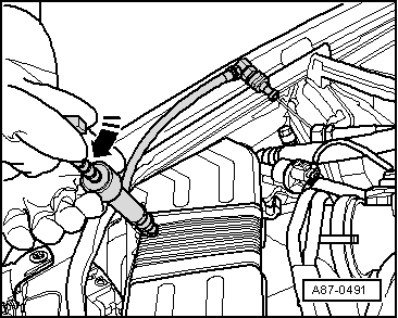
| |
Remove sealing cap from service connection of low pressure
side in refrigerant circuit. |
| |
Assemble the Leak Detection Kit -VAS6201A--1-
with the cartridge -2-Leak
Detection Kit - Cartridge -VAS6201/2-. |
Note
| Make sure the hand pump hose is completely filled with leak
detection additive. |
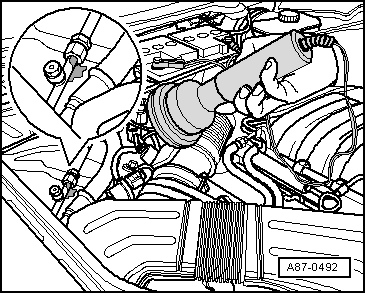
| |
Place the quick-release coupling on the low pressure side
service connection and tighten the hand wheel to open the
service coupling. Hold the hose upward and tighten the handle of
the hand pump just enough until the leak detection additive
starts to emerge from the tube. |
|
|
|
| |
Cover area around service connection on vehicle with foil or
absorbent paper. |
| |
Tighten the toggle on the hand pump to add 2.5 +- 0.5 ml
(milliliter = cm3) of leak detection
additive to the refrigerant circuit. |
|
|
|
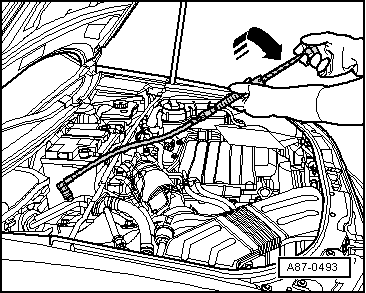
| |
Close the service coupling and remove it from the service
connection. |
| |
Remove the rest of the leak detection additive from the
service connection, for example with absorbent paper. |
| |
Seal service connection with sealing cap. |
| |
If necessary, clean area around service connection using
cleaning agents. |
| |
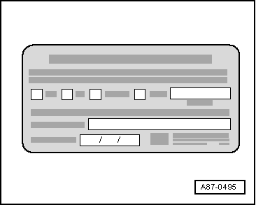
Place a label next to the service connection stating that
leak detection additive was added to the refrigerant circuit. |
Note
| The A/C system must run for at least 60 minutes so the
additive distributes itself through the entire refrigerant
circuit. The compressor must be running. Depending on the size
of the leak, it may become visible within that time. |
| |
Find the leak in the refrigerant circuit with the UV lamp
VAS6196/4. Refer to
→ Anchor. |
Note
| Remove existing leak detection additive in the engine
compartment or from the refrigerant circuit components using
Leak Detection Kit - Cleaning Solution -VAS6201/3-. |
| Detecting leaks in the refrigerant circuit using the UV Lamp
VAS6196/4 |

WARNING
| Do not look into the UV lamp. |
| Do not direct UV lamp at other people. |
|
Note
| The A/C system must run for at least 60 minutes so the
additive distributes itself through the entire refrigerant
circuit. The compressor must be running. Depending on the size
of the leak, it may become visible within that time. |
| With leaks on evaporator, leak detection additive is
possibly washed off with condensation and flows out via
evaporator drain. Since the evaporator is not easily accessible
on most vehicles, checking the evaporator drain may indicate if
the evaporator is leaking. However, it is necessary for this
purpose that leak detection additive has already been in the
refrigerant circuit for a long period of time. |
| Protective goggles do not only serve as eye protection but
also amplify the illumination of leak detection additive under
UV light. |
| Depending on the accessibility of different components in
the refrigerant circuit, it may be necessary to remove some
vehicle components such as the bumper or air filter. |
|
|
|
| |
Move vehicle into a slightly darker area of the workshop
(with daylight or bright lighting the effect of the UV light is
diminished). |
| |
Check the accessibility of the various components in the
refrigerant circuit and remove any components in the area that
block access to the refrigerant circuit such as noise insulation
and the bumper. |
| |
Wear protective eyewear to protect the eyes. |
| |
Connect the UV-lamp to a 12 volt battery (vehicle battery).
Observe the correct polarity of connections. |
| |
Switch on the UV lamp and illuminate the components of
refrigerant circuit. Locations where refrigerant, refrigerant
oil and leak detection additive has leaked out light up under
fluorescent UV light. |
Note
| The leak detection additive can remain in the refrigerant
circuit. |
| Remove existing leak detection additive in the engine
compartment or from the refrigerant circuit components using
Leak Detection Kit - Cleaning Solution -VAS6201/3-. |
|
|
 |
Note
This repair manual describes different methods for detecting
leaks in the refrigerant circuit. These methods have been tested
and result in ...
© 2016-2025 Copyright www.vwtouran.net | 0.0178

 Refrigerant Circuit, Tracing Leaks, with Electronic Leak Detector -VAG1796